Hi
In the last post, I didn't explain anything about how I made the jig which enabled the golf ball dodecahedron to be made, so I thought I'd write and picture my way through it. I will make more golf ball sculptures and jigs, but probably won't load the jigs onto thingiverse as STLs - you can work things out for yourselves and this is a bit of a how to. Programs I've used are Bricscad - excellent 2d, and Solidworks, excellent 3d.
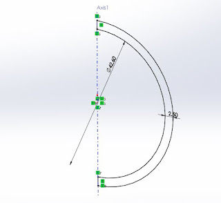 |
1. This sketch
|
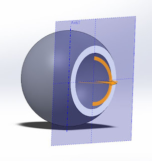 |
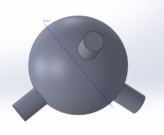
2. Is rotated around the blue axis to create a model of a sphere that could surround a golf ball.
|
The jig sits over a golf ball and aims to provide drill guides alligned with the edges of a dodecahedron. This dodecahedron has one of its 20 corners at the golf ball centre. So to start, the jig has to sit on a spherical golf ball, and the first step was (I'm just going in blind here and crashing about - you need to do this sometimes when attempting something new) to make a hollow sphere around a golf ball. The sketch (2d drawing) above shows what's rotated around the blue axis to make the hollow sphere shown in 2.
 |
3.
|
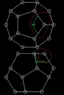
After that I need to think a bit, and went back to a 2d wireframe dodecahedron drawing I had from previous projects, shown in 3. The red lines surround 2 views of what I want to create in terms of angles between drill guides, and the white circles can represent golf balls.
 |
| 4 |
 |
| 5 |
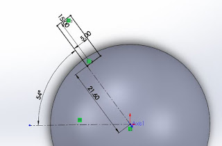
First up, I'm making bosses (sticky-outy-cylinders). The drillguide holes will go through them. I can do this with 2 sketches in the established / standard top plane, and 2 rotations the sketches around the dotted lines. The new bosses are spaced apart by a total of 108 degrees, the angle between regular pentagon sides as per the top part of sketch 4.
 |
| 6 |
The 2 previous sketches were on the established top plane, and the established front plane bisects the bosses in a way that lets us create the third equispaced boss. We just need to know at what angle to the top plane, and fortunately the second sketch of 3 gives us that.
 |
| 7 |
 |
| 8 |
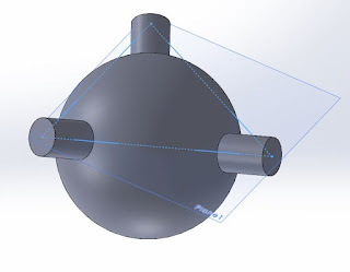
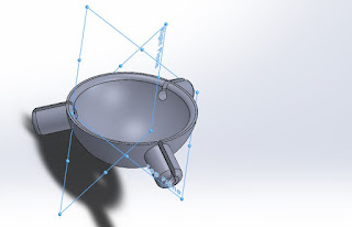
As shown in 7, we can now create our third drilling boss. We now want to create features (cuts, holes etc) that are parallel to the plane containing the outside centres of all 3 bosses. First I made a 3d sketch, then used it to define the new plane (8).
 |
| 9 |
 |
| 10 |
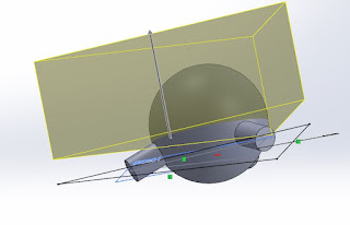
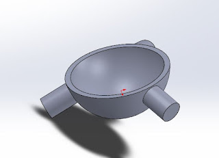
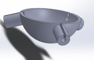
With the new plane established, I can now use the "block of cheese function" (actually cut / extrude using the new plane as a reference) to slice away part of the jig so it will fit on the golf ball as shown in 9 and 10. The height to slice at just involved trial and error. We're close to the final shape of the jig now, and the boss holes, and a few other bits and pieces just need to be added.
 |
| 11 |
 |
| 12 |
 |
| 13 |
 |
| 14 |
Once the 3 drilling bosses were added, 3 planes were added as well, and these became the sketch planes for holes through the bosses. I started with a sketch on one of the 3 new planes (11). The sketch is a slot, not a hole, and this opens things up so the bosses print cleanly (without support material) in the 3d printer - refer to the "printing" section of
this wikipedia article.
A similar sketch was done in all 3 bosses, and all the slots cut (12), and finally a few more bosses, holes and chamfers made to finalise things and make a central hole. The central hole is for a screw, so a 6g threaded timber screw about 12mm long can be screwed through the jig and into the golf ball. So this all worked, and the results can be seen in my previous post.
 |
| 15 |
 |
| 16 |
 |
| 17 |
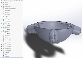
And although it worked I'm fussy! When importing the STL (3d printable file format, a bit like a 3d version of a pdf file) into the printer software, the part comes in on an odd angle, no matter which initial rotation or plane is chosen (15 and 16 show top and right planes). Also a simpler file structure is possible (17 shows current structure). This really doesn't matter as long as a workable outcome is reached, and I will show an alternative to what's done here in my next post.
 |
| 18 |
 |
| 19 |
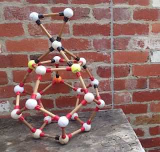
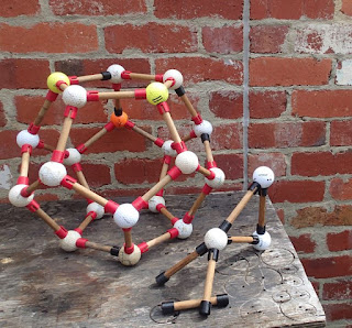
If you've gotten this far you probably deserve a break, and 18 and 19 are my latest creations / variations!
I could get 18 to balance with the dodecahedron and top triangle screwed together only, but it would fall over! Adding a few extra screws in one ball (19) made it all more stable.
 |
| 20 |
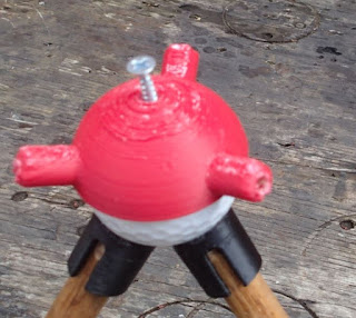
Lastly, 20 shows the drilling jig in place with its support screw. The support screw needs to be screwed down tight for the jig to be held in place.
Another version of the jig is shown in the next post.


No comments:
Post a Comment