Hi
After making a paper tetrahedron (see my last post), I have kept on working on polyhedrons which follow Marleen Hartog's pattern for a braided knitted ball. So I have made considerable progress, and have been able to work out along the way some of the theory and principles of what I've been doing.
So from the last post, I had made a paper cube as per Marlene's instructions, and had made a cane version (figure 9), and also managed to make some paper tetrahedrons. The tetrahedrons had one paper loop per side, with the paper loop completely surrounding each face, and an over and under pattern at each corner. The corners end up being mostly flat, and the assembled versions mostly spherical.
Starting with the pattern criteria that an octahedron has 4 edges at each corner, I started drawing an octahedron net based on what I'd done with the tetrahedron. The octahedron is more complex than the tetrahedron, and I took a simpler approach to making it this time, just putting different colours on white paper instead of printing outlines on different coloured sheets of paper.
So I think I've made a few "edge nets" here. The geometry nets I've heard of consist of full faces joined at hinging edges and accurately reproduce polyhedra. The joins between faces are the edges, and these are either joined like hinges "inside the pattern", or are split edges "outside the pattern". Pairs of split edges combine and coincide when polyhedra are made from nets.
The edge nets I've made consist of edges made of 2 distinct areas / struts and "roundabout" or over / under / over intersections for corners. There is nothing at actual corner points as they are at the centre of the roundabouts. A result of the 2-struts-per-edge feature is that given the correct nodes, an edge net can be made fully traversable, or made from one piece of cane. They have "two or no odd nodes" , a mathematical concept which I somehow remember from school, or engineering at uni. A long time ago!
So now I've managed to make all 5 platonic solids in this form. It makes the edge nets more complex than necessary, but also more versatile and mathematically- , and generally- interesting.
The dodecahedron was tricky and the icosahedron looked even trickier, until I realised that the edge polygons nets fit in the conventional nets of their dual. That means a cube net can be used as the basis of an octahedron edge net, and vice versa. The "rule" I used is that a dodecahedron net can be used as the basis of an icosahedron edge net and vice versa.
That is probably enough for one blog post, I will add in the pictures now. Drawings were made from scratch in Draftsight, other materials are printing ink, paper sticky tape and lamination sleeves. I plan to make a few more cane structures next, starting with the tetrahedron.
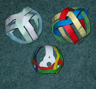 |
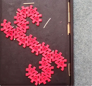
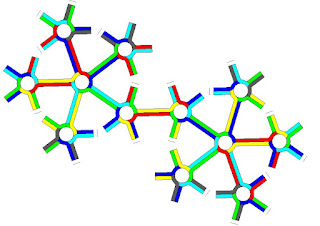
1) 3 tetrahedrons
|
 |
2) Tetrahedron edge net, makes the shape shown at the bottom of 1).
|
|
|
|
|
|
|
|
|
|
|  |
3) Conventional net for cube
|
 |
4) Edge net for cube
|
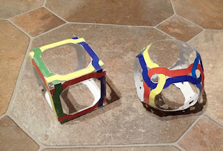 |
5) Conventional and edge nets made into cubes
|
 |
6) Octahedron edge net 1: colours surround each side, 8 loops
|
 |
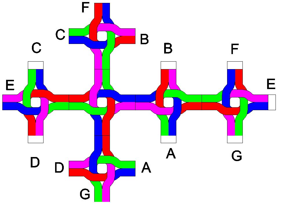
7) Octahedron edge net 2 with colours surrounding each half, 6 loops
|
 |
8) Octahedrons
|
 |
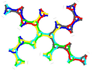
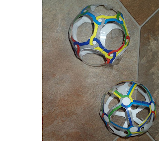
9) Conventional edge net for icosahedron made from the 3d printable construction kit available here. Playing with these helped me work out the icosahedron edge net.
|
 |
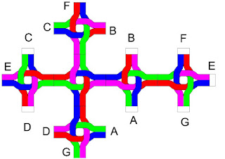
10) Dodecahedron edge net
|
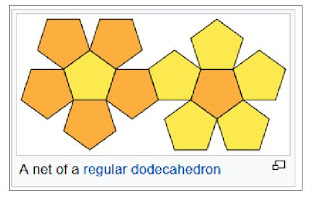 |
11) What it says!
|
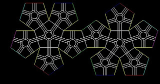 |
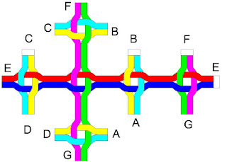
12) Above pattern with icosahedron edge net overlaid
|
 |
13) Icosahedron edge net
|
 |
14) Dodecahedron, Icosahedron
|
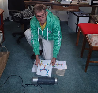 |
15) Laminating after printing
|
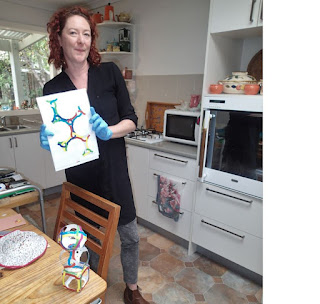 |
16) Kerrie quite liked them, we gave her a few patterns to make
|
Update June 1, 2022
Over the last 2 days, I've made and started to use a new jig which holds basket cane in the right position to make a tetrahedron based on the patterns of figure 1 above. I managed to design and 3d print the jigs one night, (17) and use them to make a tetrahedron the next.
The 2mm basket cane was soaked in water, then 1 ring was connected using heat shrink tube. The ring was then clipped into the bend jig (19) , and gradually more rings added. When all rings were in place and closed, I glued the rings together at the 3 crossing points of the nodes. When the glue was dry I removed the clips and jigs.
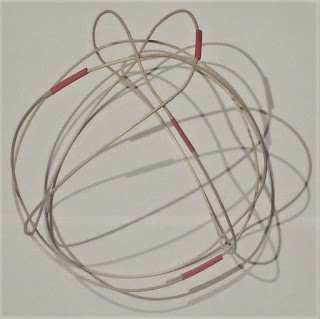
In the middle of last night I realised the photos of the finished shapes would look good on a white background without a flash, to show off the shadows, so got up and took a few photos in my pajamas, and they are shown below (20 - 22). The end shape is like an inflated tetrahedron with chamfered edges (it is topologically a cuboctohedron ) More to follow.
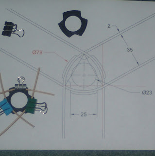 |
17) 2d drawing printed out. 3d drawing and 3d printed jigs followed.
|
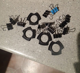 |
18) Jigs and clips
|
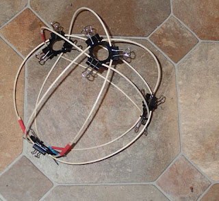 |
19) Jigs and clips in place while glue dries.
|
 |
20) Et Voila! Much easier to see what's happening in 19!
|
 |
| 21) |
 |
| 22) |
(link to next post)


No comments:
Post a Comment